This is a section of my website I have set aside for all things related to the Raspberry Pi, a range of extremely versatile single-board computers.
| Content |
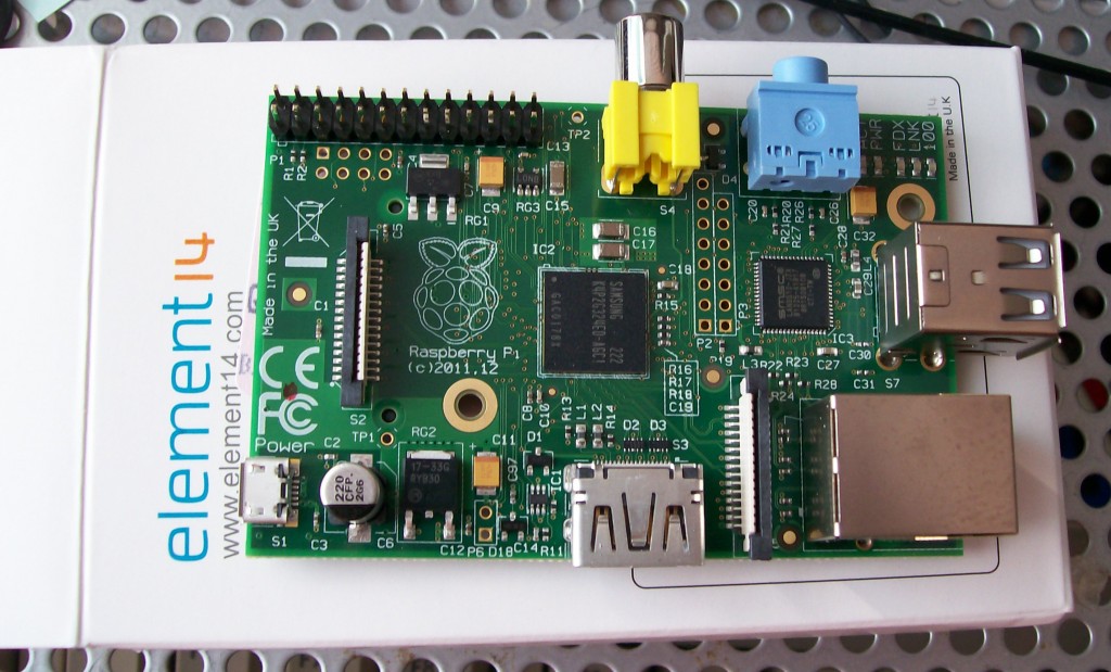
In case you’re wondering “What is a Raspberry Pi?” No it isn’t food, it is a £30 (give or take, the Pi Zero is about £4) credit card sized computer, that boots from an SD card (of which I would imagine you to be familiar with), it was created with the aims of learning how to program and also interface devices to a computer, for this it has a set of GPIO (General Purpose Input/Output) pins. It connects to a television or monitor using either HDMI, DVI (with an HDMI to DVI adaptor), or composite (the round, yellow coloured connector).
The Raspberry Pi has a 700 MHz ARM Processor (900MHz to 1GHz in newer revisions and the Pi Zero), now you may be asking “What is an ARM Processor?” and “Is the ARM Processor like the Intel/AMD one in my PC?” The answer to the first question is that the ARM processor is a low-power processor conceived in the late 80s by a UK based company called Acorn Computers (If you’re my age you may have heard of them), originally as a co-processor for the BBC Micro, also built by Acorn but using a 6502 processor, the ARM went on to be the main processor in the Acorn Archimedes series, and subsequent Acorn computers such as the A4000 and A5000. Today you can find the ARM Processor in many devices, iDevices (iPod, iPhone, and iPad), the majority of Android devices, smartphones, home broadband routers and modems, and even your digital television box, and now, of course, the Raspberry Pi. To answer the second question, I’d have to say bluntly that most versions of Microsoft Windows will not work on the ARM Processor, though Windows CE, the basis for Windows Phone and the previous Windows Mobile, and the ARM version of Windows 8, Windows RT, will run on ARM processor based systems but NOT the Raspberry Pi. Operating systems that will work on the Raspberry Pi include most Linux distributions, notably not Ubuntu however, and RISC OS, Android is being ported but I have yet to see it working on the hardware at this time. The Raspberry Pi foundation offer a choice of working OS images for download on their website, see below.
The Raspberry Pi has 256MB of RAM in the Model A and early Model Bs, or 512MB in current models of the Model B and the Model B+ released to the public in July 2014, now you may be thinking “256MB or 512MB is hardly enough for a working system” but you’ll be surprised. The Operating Systems available for the Raspberry Pi can run with this amount of RAM without much of an issue, in particular RISC OS, see below, however you cannot replace the RAM as it is installed in a PoP arrangement, this stands for ‘Package on Package’ and means the RAM is soldered on top of the processor, and your average soldering iron isn’t suitable for removing it. The 512MB version of the Model B is still below 1GB but would improve running the Raspberry Pi, especially for using it as a media centre or a small PC, the Raspbian operating system has since been updated to accommodate this memory increase in these. The original Model B can be converted to a Model A by removing some components and closing 2 links, thus giving you a Model A with 512MB RAM, however I do not recommend you do this unless you absolutely know what you are doing, this is possible because the original Model A and Model B are the same board.
With the release of the Raspberry Pi 2 Model B the CPU is changed to a quad-core ARM Cortex-A7, this is because the SoC is in fact the Broadcom BCM2836 as opposed to the BCM2835, other changed made are 4 USB ports over the two fitted to the original Model B rounded corners to the board, and a longer 40-pin GPIO header to support what the Raspberry Pi Foundation call HATs, the header is still compatible with the older Pi boards for the first 26 pins, these first came along on the otherwise identical Raspberry Pi model B+, this used the BCM2835 so was similar to the original A and B, the Pi 2 B has 1GB RAM over the 512MB found on the original Model B, the B+. the compute module (which uses an eMMC chip in place of an SD card and is in an SODIMM form factor but is not compatible with the memory slots found in laptop computers), and the Raspberry Pi Zero, released in late 2015.
The Raspberry Pi Zero, alluded to above is pretty much like the Model B/B+ with some very notable exceptions, these are as follows
- The Zero is the smallest board at a cost of roughly £4 (price listed for it is $5)
- The Zero has the pin headers for the GPIO and reset left unoccupied, these can be fitted by the end user, another header is present for the Composite video output, again unoccupied but can be fitted by the end user if they require composite video
- The Zero uses a micro USB in place of the standard USB type A, so a USB OTG adaptor is needed though some sellers are selling “shims” that convert USB type A plugs to micro USB, the power connector also uses the micro USB and is next to it, though this is labelled
- there is NO Ethernet support on the Zero, so like model A/A+ a USB to ethernet adaptor is needed along with a hub to allow keyboard and mouse except in headless use
- The board has no components on the underside, there are various pads there the end user could potentially utilise if they choose to
- The Pi Zero does not support the Pi camera or the official display due to lack of the headers to connect these
- The HDMI connector is of the mini type rather than a full type, an adaptor is needed
The Pi Zero, like the original Model B, pretty much sold out on launch day, along with the MagPi which had a Zero attached to the front of all copies of it at the time, a second wave of Zeros hit the shelves and they too sold out, I got word on twitter about a third wave from the Pi Hut and have got one on it’s way with the adaptors and the header pins and a tin that looks like it may be the size of an Altoids tin (I have an Altoids tin in the car that still has the mints in it which I bought for electronics use after I had eaten the mints), as soon as the unit arrives a test installation of RISC OS will be done on a spare micro SD, after this I have a project in mind which I shall post about later.
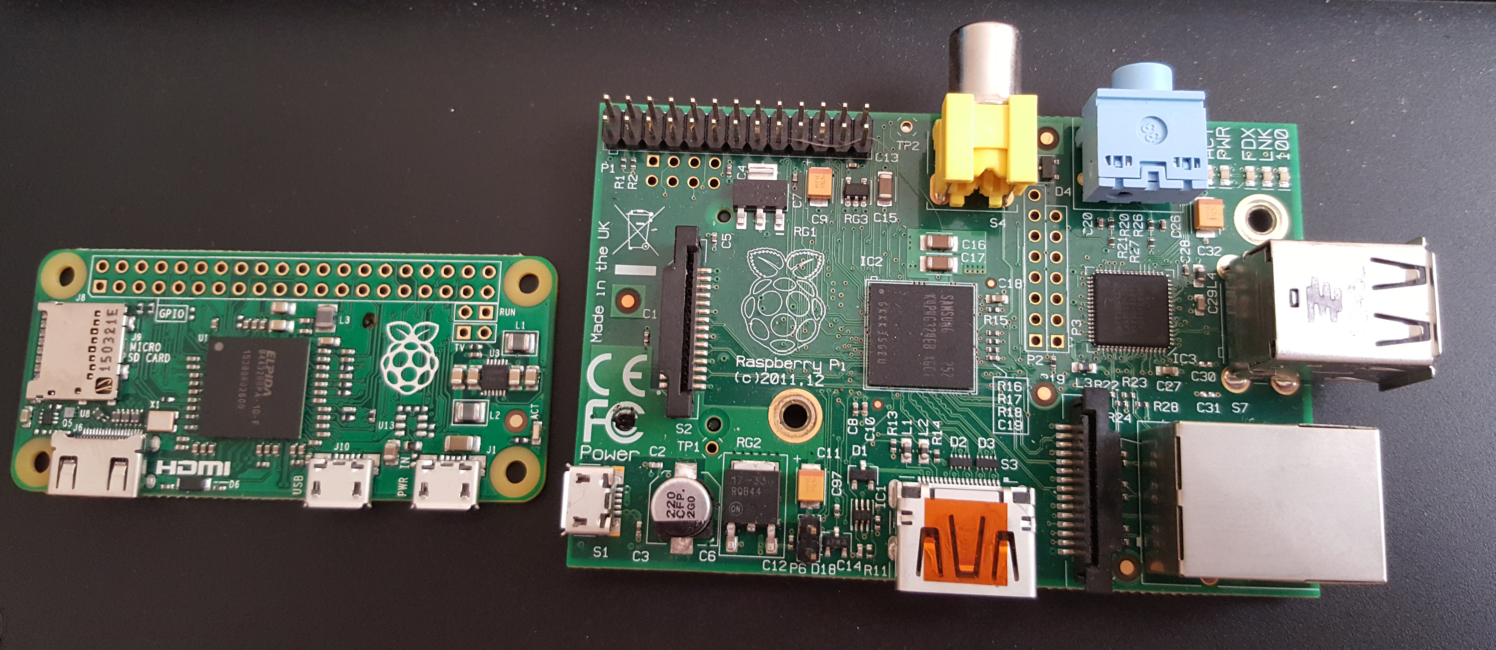
Update: I have received my Raspberry Pi Zero with the adaptors and a selection of header pins, I have yet to power up the device or even boot RISC OS on it (which I know is possible to do), the unit was a little smaller than I imagined it to be and I enclose a photo of the Pi Zero next to a Model B revision 2 (an early 512MB device)
The Raspberry Pi has an HDMI output for connection to your TV or monitor, this also can be used with a feature called CEC, which allows you to control the device with a television remote control, provided the support is available in the Raspberry Pi’s OS. Television manufacturers often give it their own name, two that come to mind are Anynet+, Samsung’s name for it, and Regza Link, Toshiba’s name for it.
The Model B Raspberry Pi contains 2 USB ports, Model B+/Pi 2 Model B contains 4 USB ports, Model A contains 1 USB port, and Zero, as noted earlier contains one micro USB port in place of a normal one so requires an OTG adaptor, these are only suited to low power devices, at least on the Model A and B, unsure about the B+, 2B and Zero as yet, so anything that requires the full 500mA normally available to USB MUST use a powered hub, also on the Model A/A+ and Zero you would have to use a hub anyway as it has one USB port.
The Model B/B+/2B Raspberry Pi has a 10/100 Ethernet port whereas the Model A/A+ and Zero lack this altogether, the LEDs near the audio out and USB ports include LEDs for network state (on Model B) including speed (10/100Mbps), to connect the Model A/A+ and Zero to the world requires a USB WiFi or Ethernet adaptor, on the Model B+/2B the network LEDs can be found in the network jack
The Raspberry Pi also has a composite output for display, though this is limited to 640×480 so it would be more practical to use the HDMI connector to connect it up to a display, on the Models A and B this is a standard yellow coloured phono connector, on the Model B+/2B the analogue audio and composite video are combined, much like a video camera, on the Zero it is an unoccupied pin header on the board
The Raspberry Pi has an analogue audio output socket on the board, though you may not need this if you are using HDMI as this connector supports digital audio as well, as mentioned above, on the Model B+ this is combined with the composite video.
The board has a set of GPIO headers which are used to control various pieces of hardware for various projects, on the Raspberry Pi you just need to create some kind of programming, in either Python or some other programming language, the possibilities of what you can do with the GPIO headers is only limited by your imagination and the capabilities of the Raspberry Pi.
On the revision 2 of the Raspberry Pi Model B and the Model A, there are some further GPIO connections that are unpopulated and set up to have the header pins soldered so they are on the underneath of the board, the pinout of the main GPIO header is slightly different but otherwise still compatible with add-on boards such as the Gertboard, before attempting to connect anything to the GPIO, I strongly advise that you take precautions against ESD. On the new B+/A+/2B there are extra pins on the main header, noted above for HATs, the above still applies with regards to ESD.
ESD stands for Electrostatic Discharge, this can cause severe, and irreparable damage to the Raspberry Pi, you can pick up wrist straps to connect you a suitable ground point (a pipe, radiator, or a grounded chassis for example) from any computer or electronics retailer, if you wish you may also use an ESD protective mat, these can also be picked up from electronics retailers.
The board has a DSI connector (except on Zero), this stands for ‘Display Serial Interface’, this allows certain raw TFT LCD panels to be directly connected,a display is available with touch support, this draws power from the Pi’s GPIO +5V, add a rechargable battery and a WiFi adaptor (Edimax recommended) for a homebrew tablet
The board has a CSI-2 interface, this stands for ‘Camera Serial Interface’, there is a camera module now available that connects to it, however in order to use it one must activate it, to do this you should use ssh or connect a keyboard and monitor, and type into the terminal the following commands:
sudo apt-get update && sudo apt-get upgrade
sudo raspi-config
The first command upgrades the Raspbian OS to include the support for the camera (most releases of the distro now have camera support, but do this anyway as good practice), the second opens a configuration tool that you will see when you first start up Raspbian, option 5 enables the camera support
You should connect and boot the Pi to do this before connecting the camera, but remember to shut down the Pi and disconnect the power before connecting the camera to it, you can find details of how to connect it on the Raspberry Pi website, they even have a video up on how to do it, just search their site for “camera board”. The CSI connector is located between the Ethernet port and the HDMI port, on Model B Pi’s with the Ethernet port fitted you may be able to rest the ribbon cable gently on the Ethernet port when you insert it into the connectot.
The other set of pins on the revision 1 board, which are not used by the end user, are the VideoCore JTAG connections, next to that is an unpopulated strip which is the Ethernet controller (LAN9512) JTAG. On revision 2 boards (pictured) both strips are unpopulated, and an unpopulated 2-pin header for a reset switch is available on the board, a PC reset switch can be connected to this but a 2-pin header would need soldering here. This connector is found near the HDMI socket.
The power connector on the Raspberry Pi is a Micro-USB type B connector, so you could power it off your mobile phone charger. The Foundation have stated that power supplies should, at least, provide 700mA (0.7A) to power the Raspberry Pi, mobile phone chargers are usually rated around about that, so far I have seen these types of charger with LG, Samsung, and BlackBerry phones.
Installing an operating system to your Raspberry Pi
To install an OS to your Raspberry Pi, you need to download an image which you need to put onto a blank SD card (note that the Model B+, A+, 2B, and Zero take microSD cards instead so you will need an adaptor to flash it with your computer), There is a small list of suitable images on the downloads section of the Raspberry Pi website, you also need a piece of software called Win32DiskImager if you’re using Windows, but if you’re using Linux or MacOS X then the dd tool should be fine here.
And here is, in a basic way, how to do it (aimed at Windows users as they account for the vast majority of computer users)
- Insert a blank SD card, 2GB or bigger, into your computer’s SD card reader/writer. If you have not a card reader/writer in your computer just use a USB one. I have chosen a 4GB SDHC card for mine, but it should be noted that you should buy from a reputable seller, not from eBay, many on eBay may look like a bargain but they are often counterfeit, poor quality, and subsequently do not work properly, and that can cause problems with the Raspberry Pi booting up.
- Download Win32DiskImager if you’re using Windows, remember where you downloaded it to.
- Download your chosen image, for most users this should be Raspbian image, there are two download options, torrent or direct, you will most likely have an easier time using the torrent, so make sure you have a BitTorrent application to hand, µTorrent is a personal recommendation of mine, if you wish to use the torrent.
- Find where you have downloaded the image, and extract it from the zip file, make a note of where you extracted it to for the next step.
- Locate Win32DiskImager, this will also come in a zip, so extract all the files to a folder, then run it, navigate within the app to where you stored the image after you extracted it, you do this by clicking on the blue folder icon at the top of the window.
- Under device, check that the letter matches that of your SD card reader, if you have no flash drives plugged in there should only be one letter. when you’re happy, press write and go make a cup of tea.
- When it’s done, click on OK, close the app, and remove the card from your computer, hopefully it will boot up your Raspberry Pi.
- Use your Raspberry Pi and make all sorts of clever things with it 🙂
Note that since I wrote these instructions the Raspberry Pi Foundation introduced what they call “New out of box software”, or “NOOBS”, this removes the need to flash a card in this way, it does the work in the Pi by allowing you to install an OS of your choice, however many, like myself, prefer the method above or the dd tool on UNIX-like systems (this includes Mac OS X).
Also note the current released image of RISC OS does not work on the Pi Zero immediately, some extra work is needed, this is to replace the firmware supplied with that from Raspbian “Jessie”, once this is done it should boot fine, the files you need are bootcode.bin, fixup.dat and start.elf, overwrite these on your RISC OS card, reinsert into the Pi Zero, and boot (this will appear to freeze at the network checking stage but is easily bypassed by hitting “Escape”, and clicking “Cancel” when a warning about the system not starting up successfully appears, just disable the network, further information will appear on my RISC OS site in due course (naturally I will be making it on RISC OS)
My projects with the Raspberry Pi
- The server running this website
- IRC bouncer
- PMCoffee
- Nokia 3310 LCD (Based on Philips PDC8544)
- Using as a regular desktop computer with RISC OS
- Timelapse with the camera board
- Jumbospot
The server running this website
For many years I ran this site from various bits of hardware, settling on a Dell PowerEdge SC1425, with the Raspberry Pi 3 B+ coming to market it made sense to switch it out to this to reduce overhead in electricity bills.
Most of my websites are now run from it, it runs headless in my living room behind my TV, powered by a Samsung phone charger and is absolutely silent, the loudest noise in the room usually is that of the fridge motor in the kitchen or the TV itself when it is operating, great idea, the feed from the third item will be sent to it at some point.
IRC bouncer
With the same Dell server I mentioned being decommissioned as a server my IRC bouncer needed a new home, I had my Pi Zero floating about and put it to work and it has run without any interruption save one power cut since the beginning of 2018 and it handles the task well, I am impressed with its performance, all I needed to to was install ZNC and configure it and I was good to go.
PMCoffee
PMCoffee is a coffee pot themed webcam that takes it’s inspiration from the Trojan Room coffee pot, the world’s first webcam. This originally made use of the Raspberry Pi with an off-the-shelf webcam, in this case it was a Technika 1.3MP webcam from Tesco, connected to the Raspberry Pi via USB, however I swapped it out for the Raspberry Pi camera board, using motion and ffmpeg to get the image from the camera. A small script on the webserver downloaded from the motion website allows it to get the images from the Pi and present them on a simple website, for a camera feed I figured a simple website would suffice, the image is set to update once every 30 seconds. Given that the Trojan Room coffee pot camera server was an Acorn Archimedes, the computer series that the ARM processor was first used in, the Raspberry Pi is the perfect machine for the job.
Given the GPIO pins on the Raspberry Pi I may be able to set up the Pi to control the coffee pot, either to power it up from a website or to set it to power on when it needs to, depending on requirements (though I’d have to make sure there was some coffee grounds and water in it first, though I need to look at how I can implement it without risking killing the Pi or the coffee pot or both, and also both the software backend and frontend, I am looking at suitable ideas however, though this will happen later, and will be restricted to operation by myself (and later my fiancée) as I don’t want the world being able to turn my coffee maker on, but that’s something to think about for another day, this means that PMCoffee is set to evolve beyond purely just a webcam. Though it is currently running on my existing 256MB Raspberry Pi I bought a new SD card with a new install of Raspbian on it for the purpose which can be directly swapped to a second 512MB Raspberry Pi later.
You can find out more about PMCoffee by clicking the link at the top of this page (hover over the link of this page to get to it), and view the camera feed itself by clicking the same link, it runs 24/7 and is lit up at night using a crude lighting system I put together that is set to come on when it gets dark, again taking inspiration from the Trojan room coffee pot, however my lighting system is not working as it should be at the moment and will be rebuilt.
Nokia 3310 LCD (based on Philips PDC8544)
I have salvaged the LCD from an old Nokia 3310, after finding out that type of display can be interfaced with the Raspberry Pi, however the ones I have seen are fitted on boards with passthrough to the contacts on the back of the display itself, which is a Philips PDC8544 (a variant of which is also used in the Nokia 5110 but with a different pin arrangement)
As I have this display I do intend to put it to some kind of use owing to the state the phone I retrieved it from was in, also, I’d not be able to reuse the LEDs that served as a backlight as these are surface mount and will prove impossible to desolder and hand solder. I can probably purchase suitable LEDs to side-mount to the display and thus provide a suitable backlight for the screen.
Sadly when trying to solder some wires to the LCD the tracks above the screen where the contact points were unfortunately were damaged, this is despite running the soldering iron at a low temperature as possible, so instead until I can get another (preferably faulty) Nokia 3310 to extract the screen from and a conductive pen so I can build my own I have ordered a pre-mounted Nokia 5110 display, this will be connected to the Pi that is the PMCoffee camera server, to indicate to me, at a glance, if it is online or not, yet work has yet to begin on that.
Using as a regular desktop computer with RISC OS
RISC OS is the operating system originally designed by the same team behind the ARM processor and found on nearly all of Acorn’s ARM based machines.
RISC OS differs vastly from other operating systems in that it has no filetype extensions, applications are simply folders with names beginning “!”, filesystem paths are seperated using “.” rather then the more familiar / or \, drives are given numbers rather than letters, for example ADFS::0.$ would historically refer to a floppy disk formatted using Acorn’s Advanced Disc Filing System, the $ represents the root of the disk, hard disks were allocated :4 when they were present.
I will be doing a full write up on a special RISC OS website.
I have found it to run faster on the Raspberry Pi than the Raspbian Linux distribution with LXDE, though it isn’t a complete replacement.
Timelapse with the camera board
This is an ongoing project, which others with the camera board have done as well as there is a feature to do this in the camera’s raspistill program, the option to do this is -tl, which takes an image every so often, specified in milliseconds, so for example you would specify this for about 24 hours and 5 minutes to get output images suited to 1080p output:
raspistill -t 86700000 -w 1920 -h 1080 -tl 300000 -o tl_%05d_img.jpg
The -t option specifies the runtime of raspistill, this is specified in milliseconds, 86700000 milliseconds is 24 hours and 5 minutes, -w and -h specify width and height, -tl is set here to take an image every 300000 ms, which is every 5 minutes, -o specifies the output file, use the %05d to place a number in the filename that changes as each file is written, it’s 5 digits padded out with zeros. (I found that out on RasPi.TV while looking for the best way to set up timelapse myself so I should credit Alex Eames for publishing that information).
I took a 3-day long timelapse video, which roughly translated to about 17 seconds when I finally processed it, I had it on YouTube before my main channel became radio communication only, I have yet to find the files and upload them to my “Internet Videos” channel but will re-embed them once I do
I then took a 4-day long timelapse out of my kitchen window (at the old house), as it faces a road there is significantly more activity.
Jumbospot
The Jumbospot is a Chinese made HAT for Raspberry Pis and is the same form factor as the Zero, as my existing Zero was already in use I bough the newer Zero W variant, which the Pi-Star firmware supports, the Jumbospot is an Amateur radio digital hotspot supporting DMR, D-STAR, Yaesu System Fusion, P25 and NXDN, it also includes some POGSAG support as well
All it needs is some headers soldering to the Pi Zero, an LED display fitting and you’re good to go once it’s put in a case (supplied in some instances) and an antenna fitting, configured correctly you can leave it to run in the background and operate with your Digital Voice radio out of repeater coverage, remember you must be a duly-licensed Amateur radio operator to do this however.
Test rig for the Raspberry Pi Camera
As I am currently working on (at time of writing, March 2019) to bring PMCoffee back to the World Wide Web, I have purposed the Pi originally used for that task as a test bed for the Pi camera, it outputs to a basic website using some code lifted from PMCoffee and the same backend (the website is here but may not always be active) and whatever camera plugged into that Pi will generally be pointed at a physical test card or a random object, as far as I can tell the older Pi versions can run the newer camera with the better image sensor, the one for PMCoffee, which is under test in March 2019, is an original (Rev 1.3) camera and seems to be working fine, other projects will use the newer camera modules as this version is no longer available, the link to the test rig page will also be on the top of the page (hover over the “Raspberry Pi” link then click on “RPi Camera tests”)
Hope you find this helpful and inspiring, more will be added over time 🙂
Updated to reflect availability of 512MB version of device and picture replaced after domain change broke original picture
Further updated to include upcoming release of camera module
Further updated to indicate the upcoming release of Model A
Updated with projects section
Updated to reflect release of Model A and some minor modifications to the page itself
Updated to reflect release of camera module
Updated to reflect new version of raspi-config utility
Updated again to reflect new version of raspi-config utility
New project, timelapse photography
Updated after a long period of lack of updates to include the Raspberry Pi 2 Model B, the Model B+. the Model A+, and Raspberry Pi Zero
Updated to include brief information on NOOBS and how to get RISC OS working on the Pi Zero
Raspberry Pi is a trademark of the Raspberry Pi Foundation